24Vin-200Vout Flyback Converter PCB
Tim ErwinSept 2020 - June 2021
Overview
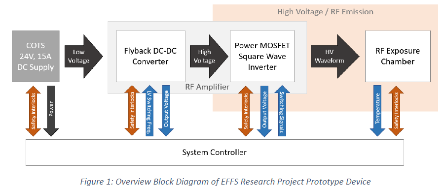
This flyback converter is a part of a device that will be used to study the effectiveness of pasteurizing low-moisture foods, such as flour, by radio-frequency heating. Major system components of the pasteurization device include a flyback DC-DC converter, oscillator, and a food chamber. I designed the flyback converter, and two other students worked on the oscillator circuit and food chamber.
The flyback converter is controlled by the LT3751 High Voltage Regulator Controller IC and monitored by an external microcontroller. The circuit supplies 200 volts to a RF generation circuit.
Software and Services:
- Schematic and PCB Design: Altium Designer
- Circuit Simulation: LTspice
- PCB Manufacturing: JLCPCB
System Overview
Circuit Design
The flyback converter is regulated by the LT3751 High Voltage Regulator Controller IC and monitored by an external microcontroller. A primary side RCD snubber was implemented to reduce the magnitude of the voltage spike at the switching MOSFET. Additionally, I designed a discharge circuit to discharge the output capacitors when the CHARGE signal is low.
PCB Design
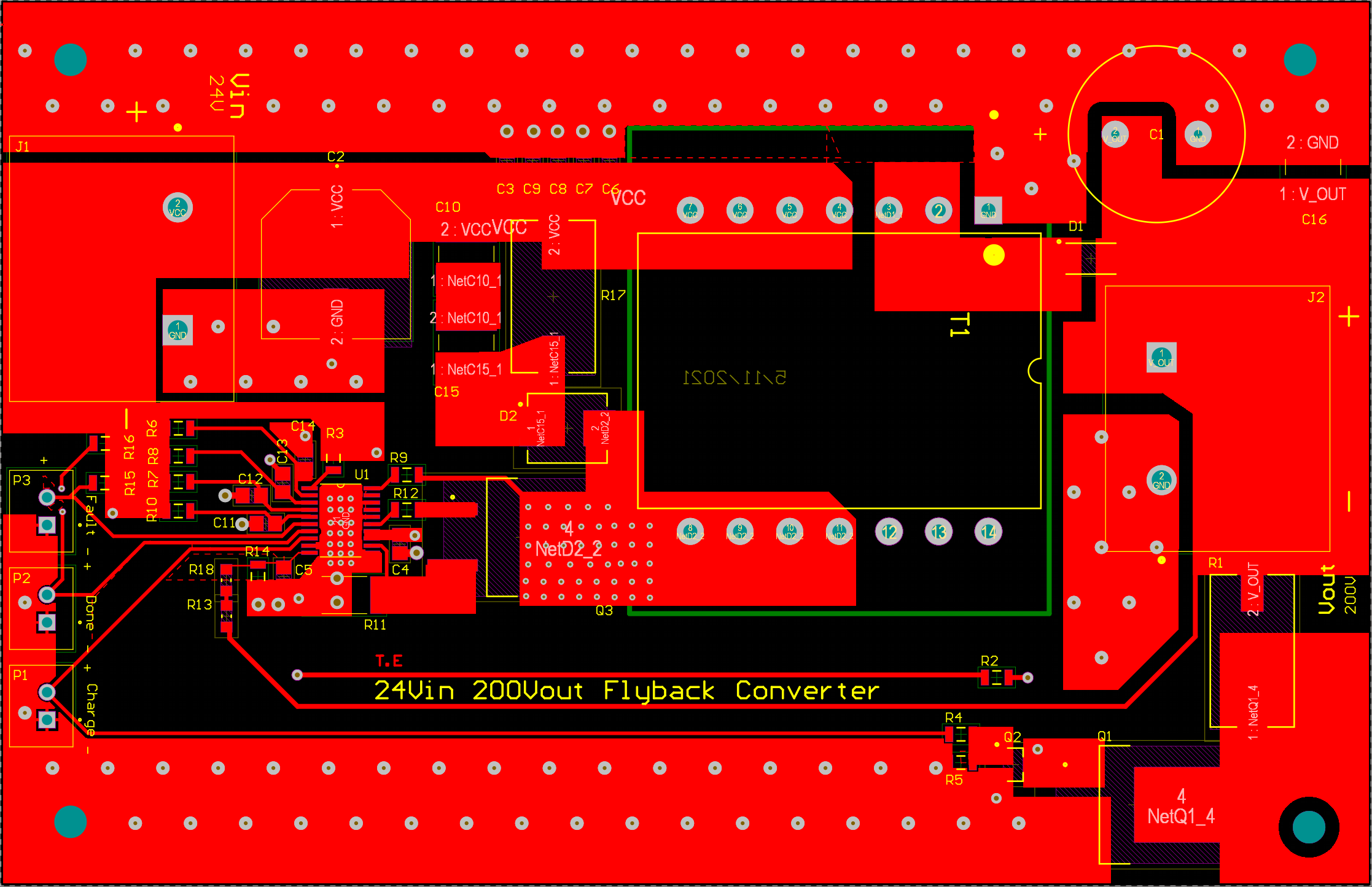
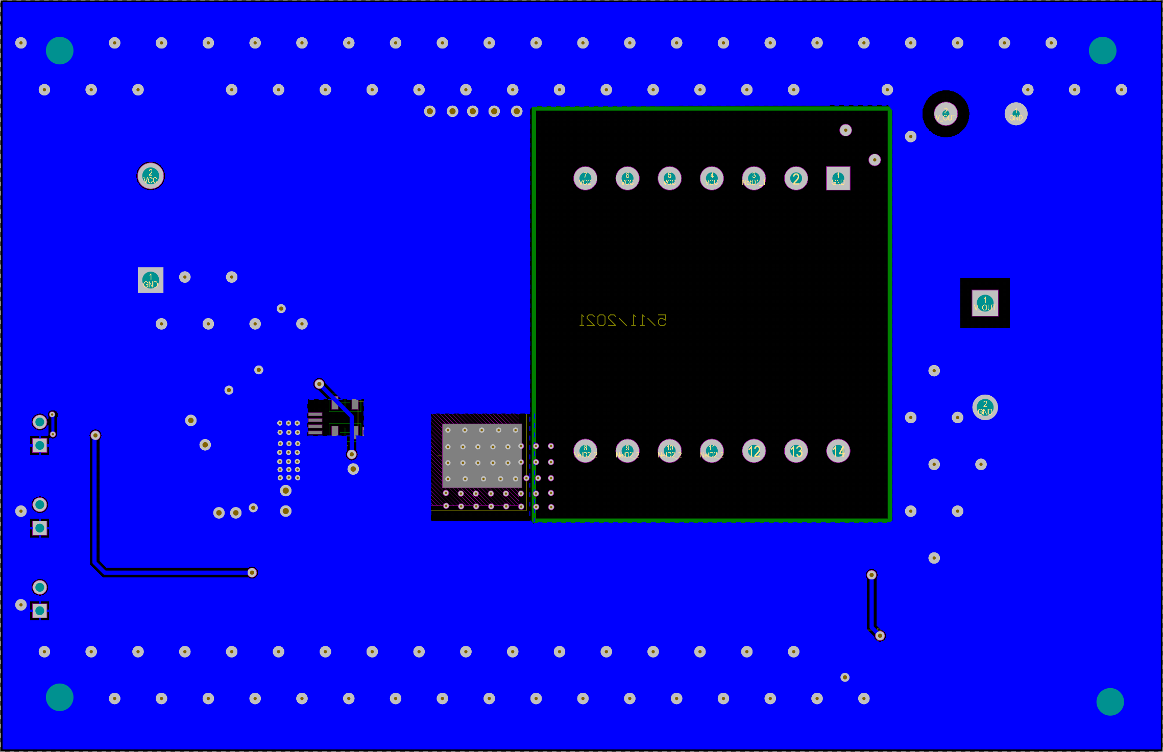
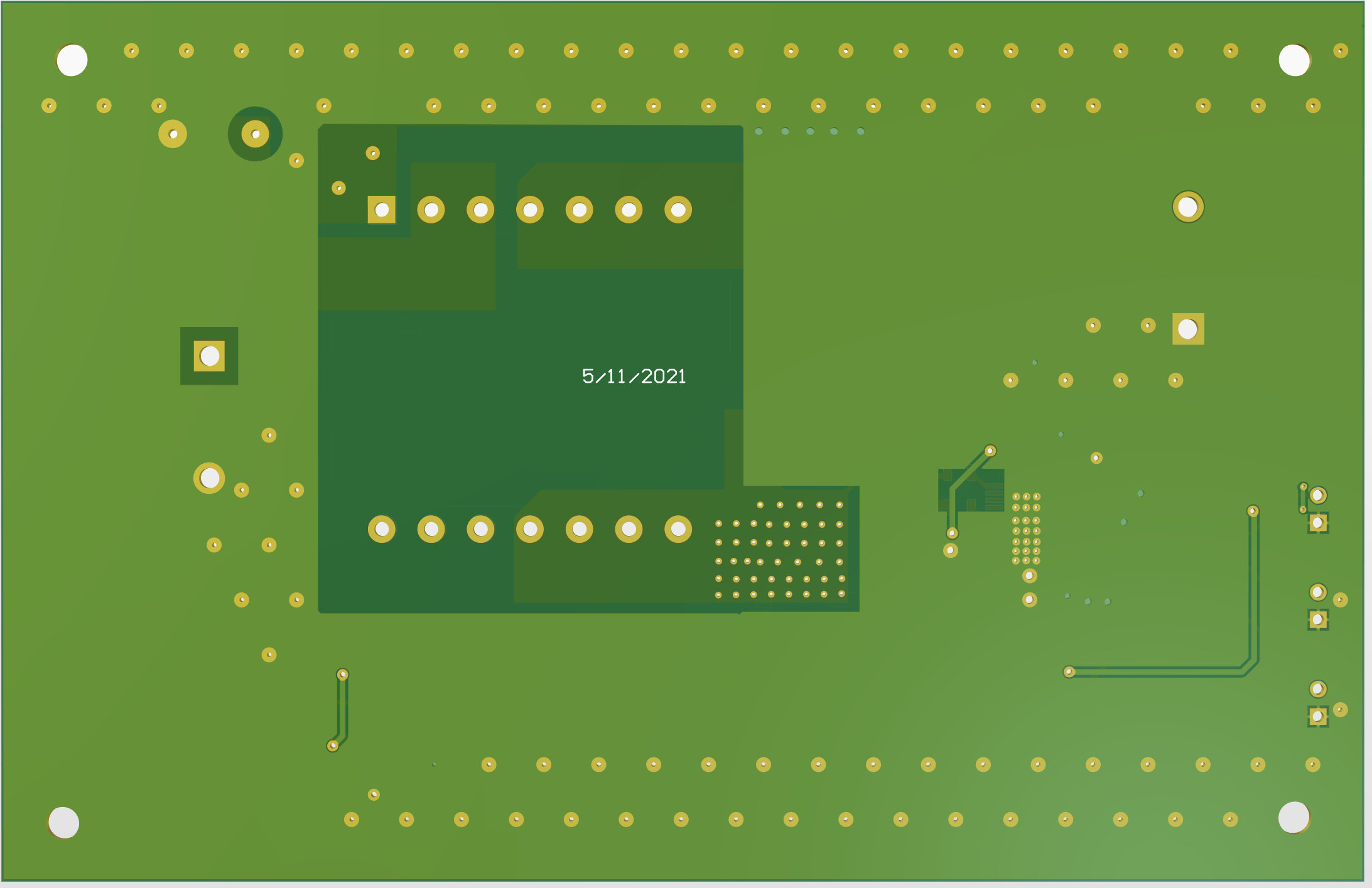
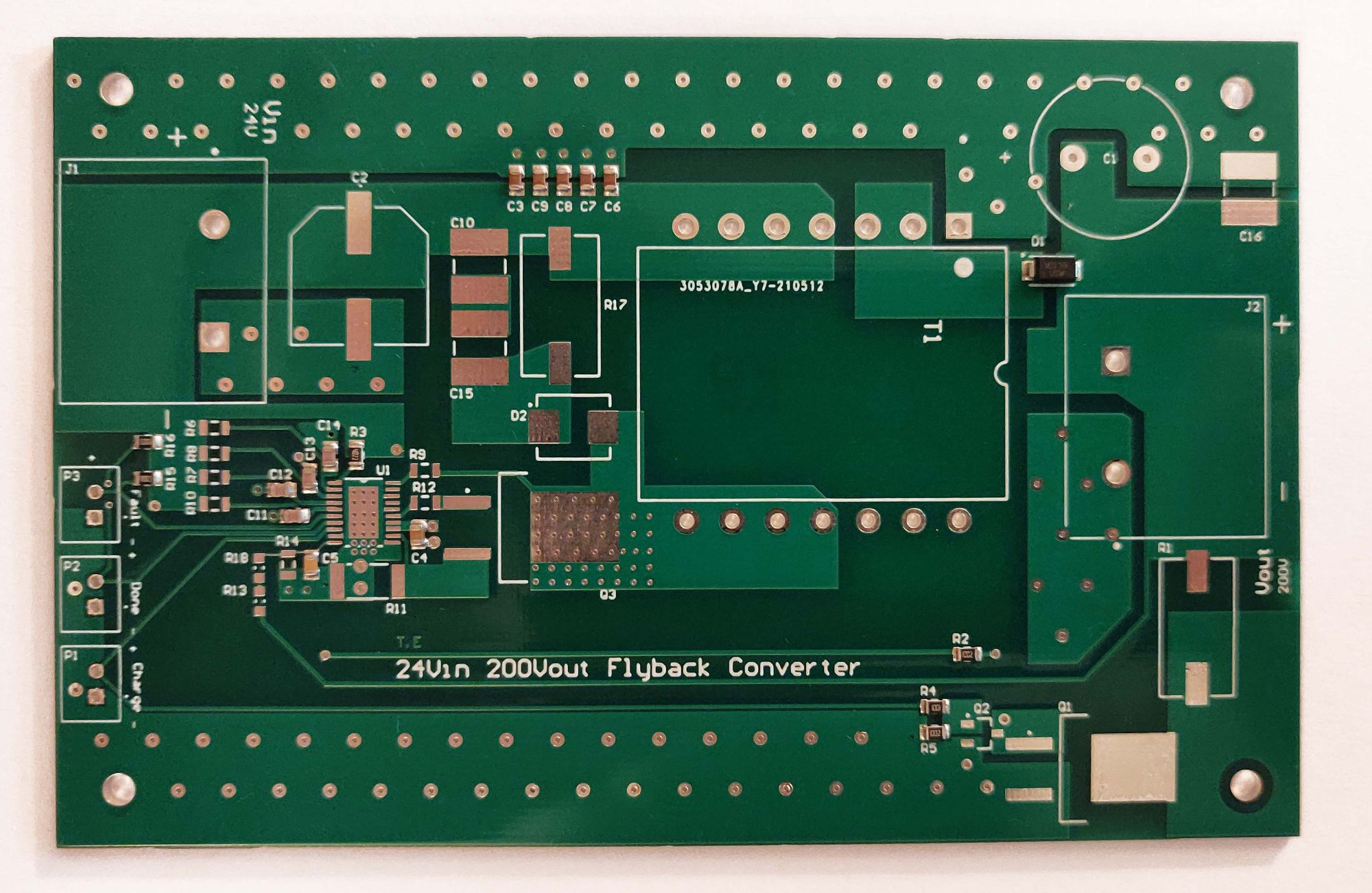
This is a two-layer board with a ground plane on the bottom layer.
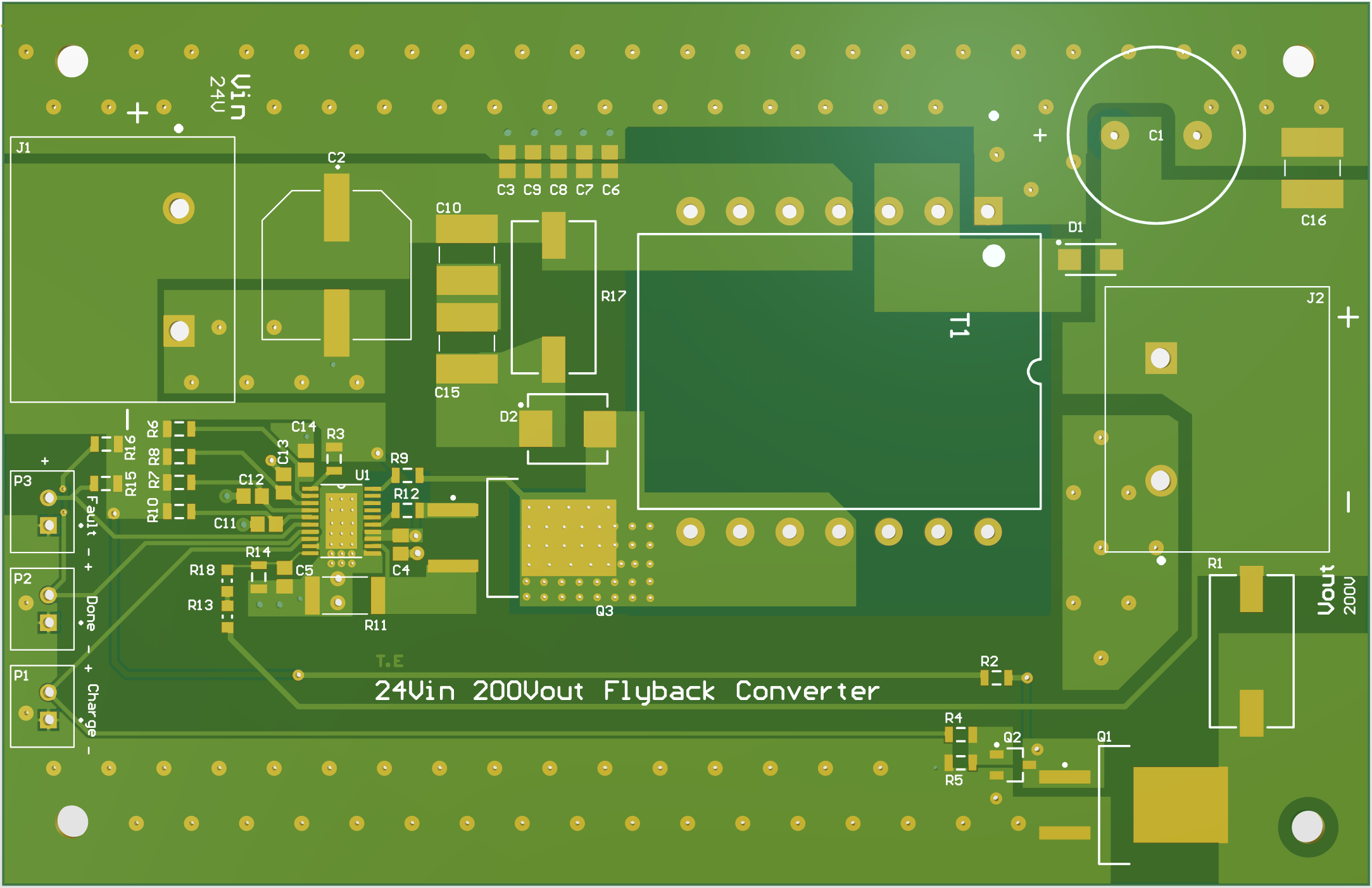
Because this is a high voltage switching converter, the PCB layout is very important. Some things that I considered while laying out the board:
- Creepage and clearance for 200V
- Minimizing area of switching loops
- Keeping input and output current loops flowing in the same direction
- Short traces
- No ground plane past transformer
- No ground plane under Rvout and Rdcm nodes to reduce capacitance
- Keep feedback trace far from transformer
- Thermal management.
Assembly and Testing
PCB Assembly
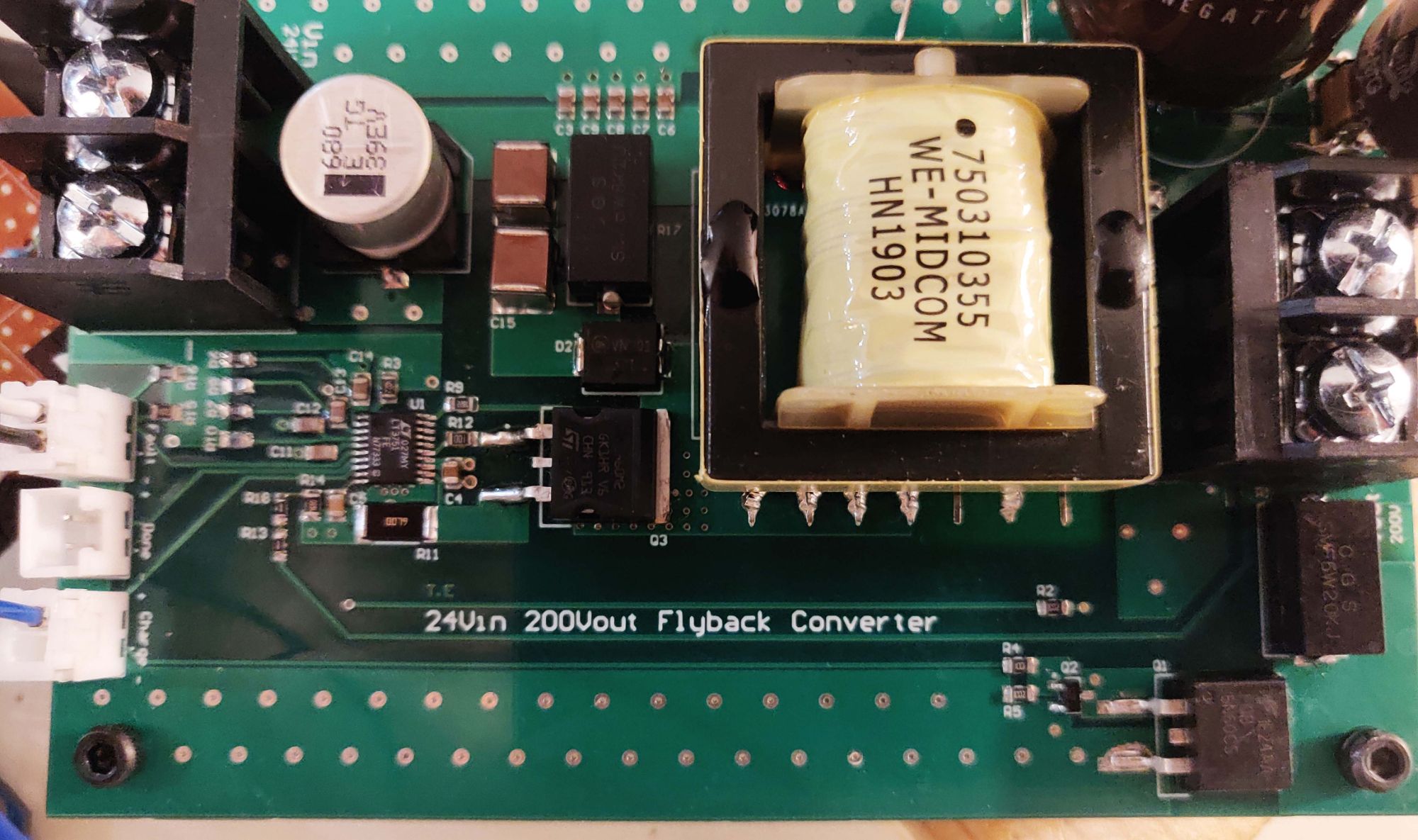
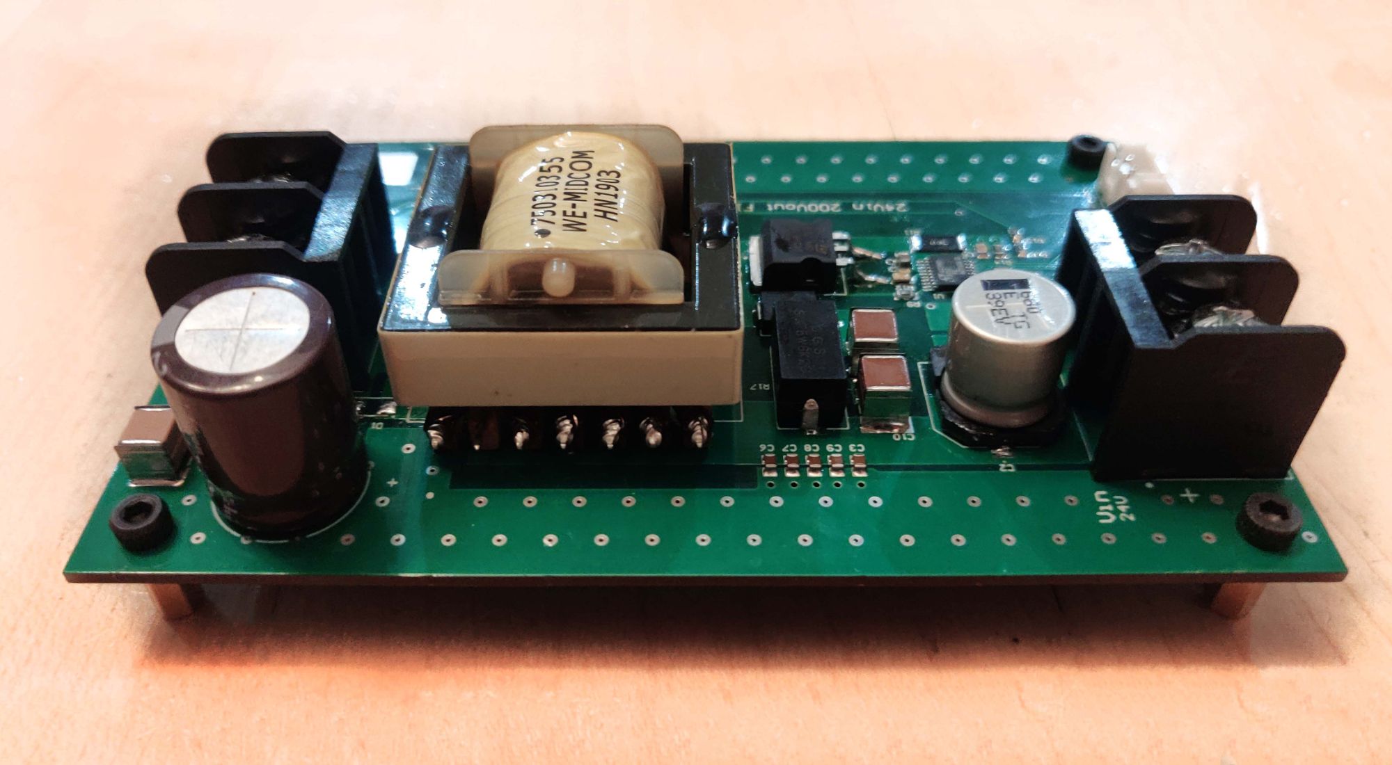
I had a few surface mount components soldered by the PCB manufacturer, JLCPCB. I soldered the remaining components.
Testing
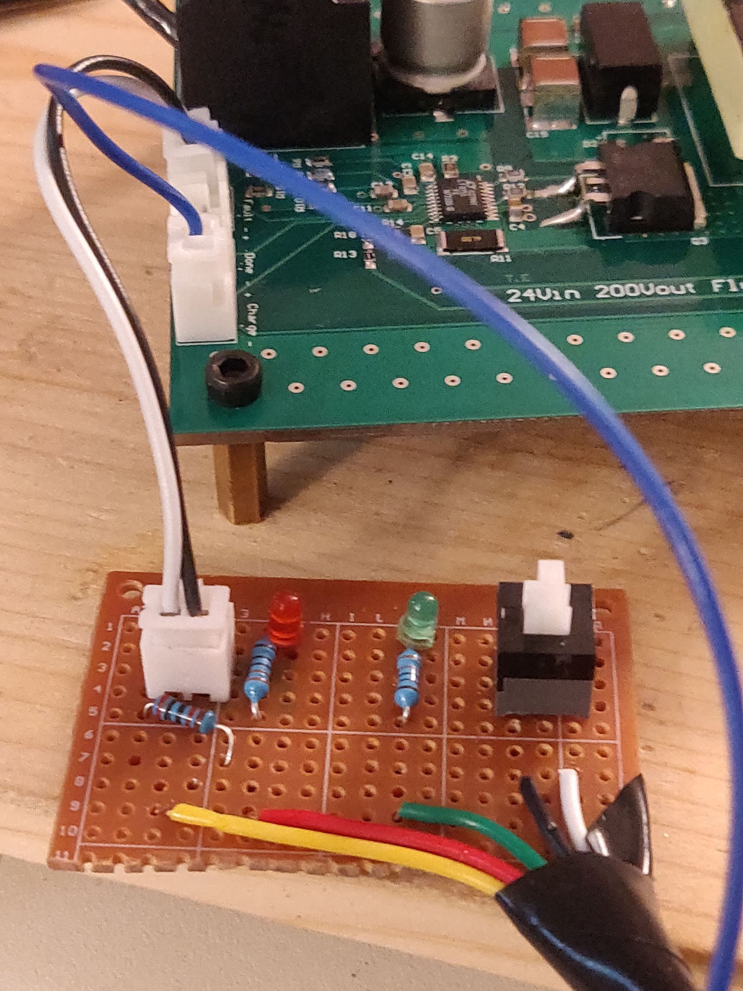
I made an external circuit to safely enable and disable the flyback converter. The green light means that the CHARGE signal on the flyback PCB is high. If only the green light is on, the flyback converter is operating. If the red light is on, the flyback converter controller IC is not switching because Vcc fell below or went above the threshold voltages. An Arduino monitors the FAULT signal and provides the 5 volts to the converter's enable pin.
As seen on the multimeter below, the flyback converter PCB outputs 200V when there is no load attached to the output. When there is a load, the output voltage slowly drops. Increasing the output capacitance helped to maintain a higher voltage for longer, but it still falls back down. I did not have access to more high voltage electrolytic capacitors so I was not able to test the flyback converter with more output capacitance. When I first tested the flyback converter with a load attached to the output, the output diode broke, probably because it couldn’t handle the current (even though I used the diode that the LT3751 datasheet recommended). To fix this, I used a large diode that I had at home. I used three in parallel to ensure that they could handle the current. The output diodes gets very hot when there is a load attached to the output. Because of this the flyback converter cannot be operated for long periods of time with a load.
Next Steps:
Next steps include investigating the why the circuit cannot drive a load and why the output diode overheats. Ideas to begin troubleshooting the circuit including adding more output capacitance and replacing the rectifier diode with a suitable ultra-fast recovery diode. Implementing an RC snubber on the output diode may also be helpful.
