Overview
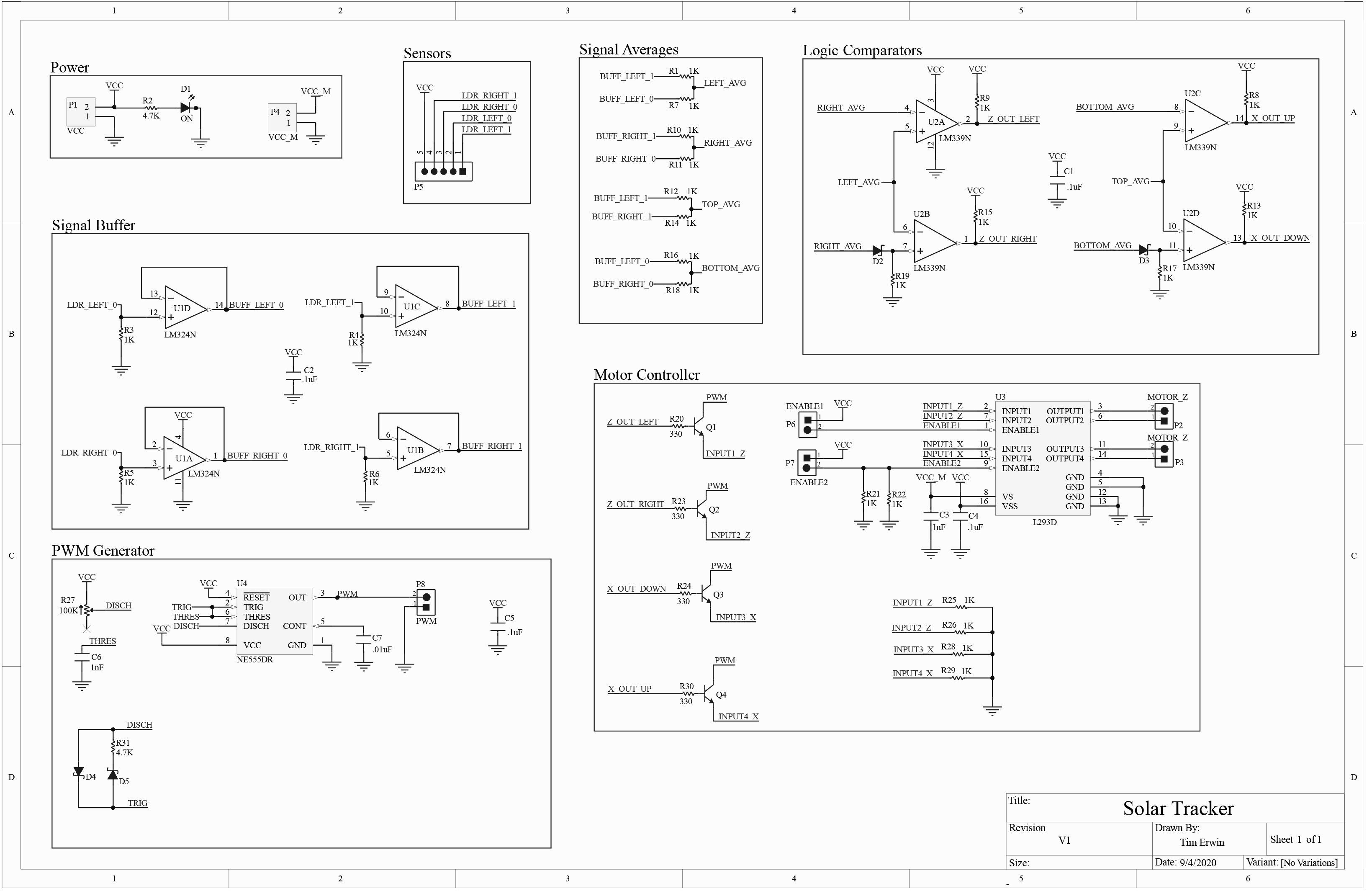
I designed a circuit that controls two motors in order to track a light source moving along two axis. The circuit utilizes four photoresistors (LDR) to detect the position of a light source. The logic for controlling the motor direction is done by several comparators. An H-bridge and PWM generator drive the DC motors.
To test and demonstrate my circuit, I designed and 3D printed a prototype mechanism that follows a light source along one axis. In the future, I plan to design a solar tracker mechanism that is capable of moving a solar panel along two axes.
Software and Services:
- Schematic and PCB design: Altium Designer
- PCB Manufacturing: JLCPCB
- 3D Design: Onshape
Circuit Design

Input
The inputs for this circuit are the output voltages of four voltage dividers comprised of photoresistors LDR_LEFT_0, LDR_LEFT_1, LDR_RIGHT_0, and LDR_RIGHT_1, and resistors R3-6. Because each resistor tied to ground has a constant resistance, the output voltage is dependent on the light intensity at each LDR. These output voltages are then buffered by U1 (a quad opamp IC), and averaged by a passive averaging circuit.
Logic
The averages of the left and top side (AVG_LEFT and AVG_TOP) of the LDR board are the inputs to two "reverse" window comparator circuits (U2). The upper voltage references of these window comparator circuits are set by RIGHT_AVG and BOTTOM_AVG. The lower voltage references are set by lowering RIGHT_AVG and BOTTOM_AVG by a constant voltage (around 0.7 volts) with diodes D2 and D3. Depending on whether or not LEFT_AVG and TOP_AVG are higher or lower than their upper voltage references, the "reverse" window comparator circuit will output signals to rotate the LDR board about the X and Z axes. The solar tracker mechanism will move until the LDR board is facing the light source. At this point, all four LDRs will be exposed to an equal amount of light, and LEFT_AVG and TOP_AVG will be in between their two reference voltages and all comparator output signals will be low.
Motor Control
The speed of both motors are controlled by a PWM signal (generated by U4), and the direction is controlled by an H-Bridge (U3). The PWM duty cycle can be adjusted from 50% to 91% with R27.
Testing The Circuit
Testing the circuit on a breadboard
PCB Design
The pcb has four layers. The inner layers are dedicated to power and ground planes. I made the voltage divider resistors (R3-6) through-hole components so that they can be easily changed to different values depending on ambient lighting and intensity of the tracked light source. The input enable pins can be set to low via jumpers on the ENABLE1 and ENABLE2 headers depending on how many axes the circuit will be controlling. I included a header on the PWM signal output so I can use the board's adjustable PWM generator for other experiments and projects.
Assembled PCB
Mechanism Prototype
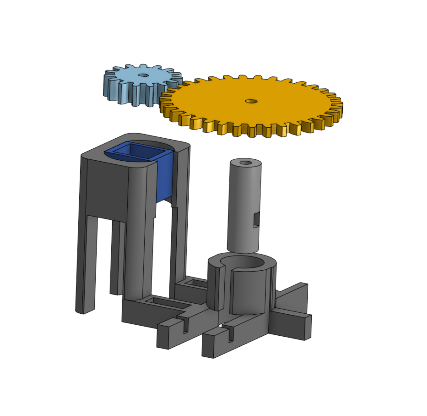
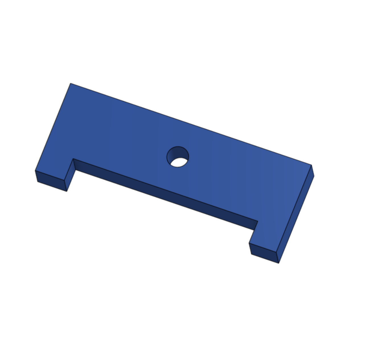
I designed and 3D printed a single axis solar tracker prototype. Components include: motor and slip ring stand, two gears, shade maker (for dual axis tracker), shadow fin (for single axis tracker), and an adapter to attach the shaft to the slip ring.
3D Models
Future Plans
In the future, I plan to design a mechanism capable of rotating a solar panel about two axes. A possible future project could be controlling the solar tracker with a microcontroller.


